MpCCI Mapper

The crash behavior of relevant components does not only depend on design geometry and material properties, but is also influenced by manufacturing history. A failure can be caused by local thickness reduction or residual stress peaks which are a result of the stamping process. This failure can limit the functionality of the entire component. In particular, the local hardening step can induce gradients in the phase proportions or influence residual stresses – and thus influence the dynamic behavior of the crash part.

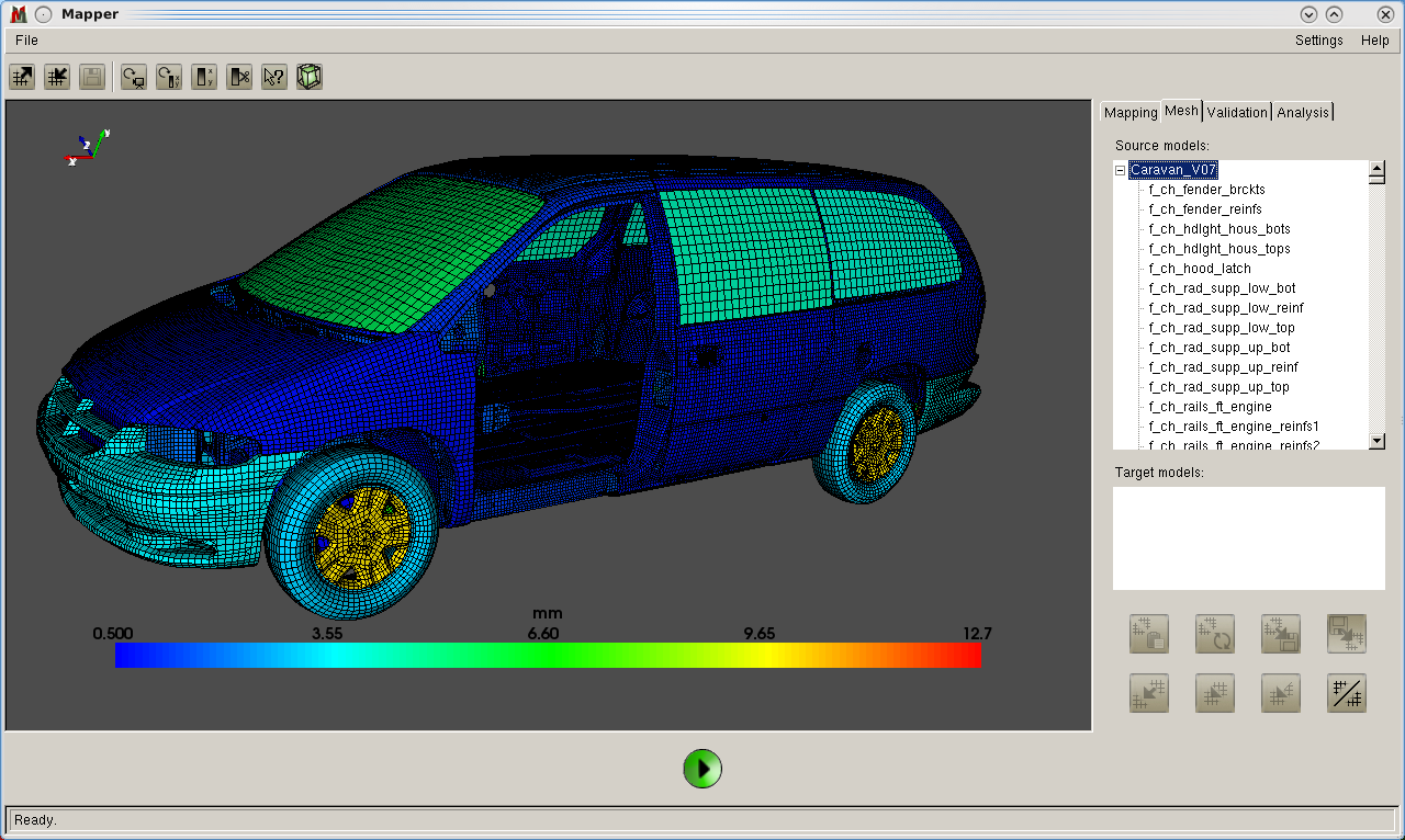
MpCCI Mapper allows to check the geometric compliance of two models by calculating the local distances between them. The (automatic) mesh alignment helps to adjust the positions of two models if they are not in a non-conformal coordinate system. A robust mapping algorithm enables the transfer of various physical quantities (with nodal-, element- or shell-layer based locations) for all standard shell element and mesh types. The mapping works for different integration types as well as for different number of integration points in thickness direction for source and target model.

By using a so-called »back-mapping validation« the user can check and estimate the influence of locally incompatible mesh discretizations on the mapping quality. In a similar way, the user may compare experimental data (e.g. from forming analysis tools like Atos, Argus, or Autogrid) with simulation results. The MpCCI Mapper can provide local quantity difference images, which then can be used to adjust the parameters of the forming simulation.

Concept

The MpCCI Mapper comes with a graphical user interface where all relevant parameters for the mapping can be set. The usage of the tool is quite simple: after selecting the models and parts some choices concerning algorithms and parameters have to be made.  The immediate visualization of the results makes it possible to detect model errors or bad mapping results due to parameter problems. The user can identify the critical areas and start a new mapping process.

The graphical user interface of the MpCCI Mapper is split up in four major regions. The main viewport where loaded models and quantities can be interactively displayed is located on left of the window. A list of buttons above the viewport form the so called 'toolbar‘ where basic operations of the MpCCI Mapper are linked. A panel region is displayed nearby the viewport, where the mapping, the list of meshes and parts, the validation of mapping and also certain quantities can be analyzed. At the bottom of the window, a single button is present which is responsible for starting mapping, validation, or analysis processes.

MpCCI Mapper uses a k-nearest-node mapping algorithm (default k = 4) that combines robustness with data smooting. At times where averaging of certain entities is not wanted or when data smoothing shall be increased, MpCCI Mapper allows to adjust the number of data points used for interpolation.

Graphical user interface of MpCCI Mapper "This model has been developed by The National Crash Analysis Center (NCAC) of The George Washington University under a contract with the FHWA and NHTSA of the US DOT"
© Fraunhofer SCAI
Graphical user interface of MpCCI Mapper "This model has been developed by The National Crash Analysis Center (NCAC) of The George Washington University under a contract with the FHWA and NHTSA of the US DOT"

This model has been developed by The National Crash Analysis Center (NCAC) of The George Washington University under a contract with the FHWA and NHTSA of the US DOT

Major Features

  • Automatic model positioning
  • Mapping
  • Validation
  • Analysis
  • Post processing

File Interfaces


The MpCCI Mapper supports most of the leading file formats for forming/stamping, structural analysis, and crash behaviour. The MpCCI Mapper also supports a growing number of formats for (photogrammetric) measurement tools.

Further interfaces are under development. If you are interested to map your own file formats through MpCCI Mapper, we would be happy to support you.


Supported Simulation Disciplines and Codes

Metal Forming

  • LS-Dyna
  • PAMStamp
  • AutoForm
  • RADIOSS
  • Indeed
  • Forge
  • MSC.Marc
  • Simufact - Forming

Crash / Structural

  • LS-Dyna
  • PAMCrash
  • RADIOSS
  • Abaqus
  • ANSYS Mech.
  • MSC.Nastran
  • MSC.Marc

Welding

  • Abaqus
  • ANSYS Mech.
  • Simufact - Welding
  • Sysweld

Injection Molding

  • Autodesk Moldflow
  • Cadmould

Composites

  • LS-Dyna
  • Abaqus

Measurement

  • Argus / Aramis
  • Atos
  • Autogrid
  • STL

Additive Manufacturing

  • Simufact - Additive


Supported Quantities

Mechanical

  • thickness
  • stress
  • strain
  • plastic strain
  • pressure
  • material orientation
  • orientation tensor
  • local material properties

Thermal

  • temperature

Release Notes

Version 4.7.0 (Jul 2021)

GUI related changes and new features

  • 'Recent Files' menu for source and target models
  • User defined quick translation or scaling of source and target models
  • Periodic and translational replication of source models
  • New solid thickness computation algorithm
  • Nodal displacement applicable to source and target meshes
  • Customization of background color and color map scheme

Solver formats changes and extension

  • New source format Moldex3d
  • New target format OptiStruct
  • LSDyna
    • ELEMENT_SHELL_COMPOSITE with material assignment from local fiber orientation
    • Redefine element integration scheme from input
    • MATFEM material orientation for invariant node numbering
  • Moldflow
    • Mid-plane meshes support
    • *.ele* files with fiber orientation tensor result can be imported for mid-plane meshes


Version 4.6.0 (Dec 2019)

GUI related changes and new features

  • New mapping algorithm for quantity ORIENTATION TENSOR, based on Log-Euclidean framework
  • Quantity validation has been extended by a statistic report measuring minimal and maximal differences in data together with an arithmetic mean and standard deviation information 
  • Quantity plot feature added to display the relative distribution of a quantity 
  • Change display of quantity units in toolsbar quantity dialog and quantity range clip dialog 
  • Transformation matrix storage option for LSDyna added; create INCLUDE TRANSFORM card for source or target model 
  • Disable or enable mapping quantities in quantity context menu 
  • Pyramid element with five nodes has been added to MpCCI Mapper

Solver formats changes and extension

  • MSC.Simufact Welding, Forming and Additive
    • Universal file format redesigned as standalone interface
    • Multiple bodies in single model now supported
    • Support for layered solid elements
    • Card 2414 format extended for data on integration points
    • Automatic detection of STRESS, PLASTIC STRAIN, TEMPERATURE and DISPLACEMENTS
  • LS-Dyna
    • Export of DISPLACEMENTS as deformed geometry and export nodal TEMPERATURE
    • Enhanced support for MATFEM model material orientations
    • Redefinition of element formulation (Elform) and through thickness integration scheme for target models
  • Moldflow
    • Geometry model file *.udm supported
    • Import multiple *.xml on file open process
    • Transient *.xml files supported; last defined state is used for import
    • Optimized IO performance on XML data
  • ANSYS Mechanical APDL
    • List of supported solid elements has been extended
    • INISTATE result format redesigned
    • Export of DISPLACEMENTS as nblock with deformed nodal coordinates
  • Vendor-neutral standard for CAE data storage format VMAP added 

Version 4.5.2 (April 2018)

  • Graphical user interface has been redesigned and is now QT based
  • Validation concept has been redesigned and is now available for all quantities
  • Enhanced scriptable batch mode using configuration file
  • Enhanced data visualization for tensor and vector quantities
  • Abaqus export of shell section composite when mapping fibre orientations
  • ANSYS export support for THICKNESS variable
  • COPRA FEA reading support (based on MSC Marc)
  • LS Dyna history variable concept has been extended to assign higher history ids than defined
  • MSC Marc .t19 result file reading support
  • Moldflow can handle multiple XML-based result files at once
  • MSC Nastran SOL 700 write support for stresses and strains

Version 4.4

  • Volume to shell element mapping algorithm improvement
  • Mapping of Indeed results now supports quantity STRESS
  • RADIOSS state format supported for writing
  • Interfaces to codes ANSYS and Forge added
  • Added additional alignment options in batch mode (-coarsealign and -finealign)
  • Slicing to plot over unwinded model length is now setup from target model extension
  • Display of vectorial quantities by length and direction
  • OpenMP version improvements

Version 4.3

  • Volume to volume and volume to shell element mapping support
  • Added support of volume elements in LSDyna reader (c.f section 4.3)
  • Converter AutoForm R4 (A213 732 0716) .csv to LSDyna keyword (c.f section 4.2)
  • Allow model alignment in batch mode (c.f section 3.13)
  • Fixed automatic result file detection in batch mode
  • Configurable view background color (c.f section 3.2.3)
  • Display of quantiy PLASTIC_STRAIN changed from average to maximum element value